Buck Converter Circuit Diagram Using Mosfet Low-side Buck (s
Buck converter circuit with mosfet pic microcontroller in proteus Bootstrap buck converter mosfet capacitor highside explained nmos Electronic – buck converter mosfet (irf4905) heating up – valuable tech
Electronic – Buck converter MOSFET (IRF4905) heating up – Valuable Tech
Buck converter Buck converter circuit using ic 555 and mosfet – diy electronics projects Low-side buck (step-down) converter
How a buck converter works
Buck converter with mosfet with the sensing resistance layoutBuck converter using low side n-channel mosfet Buck converter circuit ic using mosfet transistor electronics whileBuck converter with mosfet with the sensing resistance layout.
Buck converter uses low-side pwm ic-csdn博客High power high efficiency tl494 buck converter circuit diagram Mosfet buck converter circuit using ic electronics side switch[blog] the buck converter.

Buck converter using low side n-channel mosfet
Buck tl494 transistor circuitdigest circuitsTl494 adjustable switching power supply (universal buck boost converter Buck converter schematic power supply figure electric simulating notesConverter buck mosfet inductor using components altium pcb selecting limitation but.
Buck converter circuit with mosfetBuck converter circuit diagram using mosfet Buck converter circuit using ic 555 and mosfet – diy electronics projectsHigh current buck converter circuit.

Buck converter simulation: power design- power electronics news
Electronic – low side n-mosfet buck converter – valuable tech notesBuck converter circuit design Buck converter proteus mosfet microcontroller circuit projectiot123Bootstrap circuit in the buck converter explained.
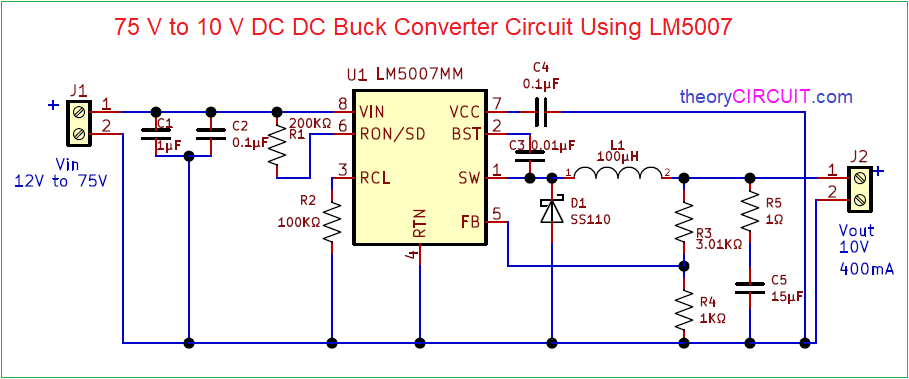
75v to 10v dc dc buck converter circuitStato tubatura agitazione buck boost inverter circuit in modo Buck converter mosfet ne555 ic timerBuck converter mosfet schematic circuit using help nmos circuitlab created stack.
![[Blog] The Buck converter](https://i2.wp.com/components101.com/sites/default/files/components/Buck-Converter-Circuit.png)
Buck converter circuit diagram using mosfet
P-mosfet buck converter (switching power supply)Buck converter with mosfet as a switch Simple buck converter circuit diagramWhat is buck converter? operating principle and waveform representation.
Electrical – how to turn on high-side mosfet of a buck converterBuck converter mosfet power supply switching circuit circuitlab public circuits description model tagged Buck converter mosfet driverBuck converter circuit diagram using mosfet.

Buck converter circuit diagram using mosfet
Buck converter circuit using ic 555 and mosfet – diy electronics projects .
.


